Posts

Showing posts with the label FEA

How not to mesh ?

Image
 Hey guys, I know this is too late but today we are going to discuss how we did not mesh to our FEA geometry to get successful results. So without wasting time let's get into it. 1) Back-to-back triangle should be avoided. Two tria elements should not be connected to each other directly. You can see this in this image. 2) On the plane surface triangular elements should be avoided. The recommended mesh is shown in the figure. 3) No mesh transition on the constant radius fillets/curvatures. Mesh transition should be carried out on the plane surface. As you can see in the figure this should not be recommended. 4) Avoid tri element on the outer edges and holes. It can cause the wrong results. 5) Some useful and recommended points that are not respectable at the professional level. This is shown in the following figure. 6) Circular hole should be molded carefully with a washer it means fine meshing at the circle. And minimum 2 layers around the hole. 7) Holes should be molded with an ev...

Quality Checks (PART II)

 Hey guys, As related to the previous part we are going ahead with the quality check as we are discussing How to improve the quality of poor elements? For this, I have search too much and spend too much time but I found very few points. But these points really get into work for everyone. This blog post is going to be small but worth in knowledge, So let's take a look at which points are those. 1. Manual Adjustment: Let's talk about the oldest technique which is only there a few years ago which is. This method consists of manually translating the nodes in today's software we can't just manually translate the nodes we have to remesh it. So we can directly remesh the part where the mesh quality is poor. This method is time-consuming 2. Auto quality improvement program: As its name suggest that all work is done by the special programs. Just we have to give the body for the program, the program automatically meshes the body to improve the quality. A special software program ...

Quality Checks (PART I)

Image
 Hey Guys, Today we are discussing an important topic which is, How we can check our mesh? Is it right? according to the ideal shape? and how can I correct it if it is not? Firstly understand that this Quality check has two parts in which are Part I and Part II will be posted very soon.  So, now let's understand why quality checks? When we carry the meshing for a complex geometry our mesh is get distorted from its ideal shape. Every element is designed to work properly within a certain range of shapes of distortion. Exactly how much distortion it depends on is get known to us by the quality check of mesh.           The Ideal shape for a Triangular element is an Equilateral triangle and for that of quad elements, it is square. And for the tetrahedron element is a regular or isosceles tetrahedron and for Hexahydron it is a cube. When we assume the actual shape or ideal shape of our mesh and place it in the model, the shape may differ from its natura...

TYPES OF SHELL MESHING AND ELEMENT OPTIONS

 Hey guys, Hope you are doing well, in today's topic we are going to discuss the shell meshing and its types and some important question that you will get after, we have talked about so many sections. So let's start with what is shell meshing? and how it works. shell meshing is nothing but simple meshing which includes 2-D mesh on the surface which is either quilt or on the mid surface or at the boundary. In this type of meshing, the software generates the 2-D mesh of quad or triangular elements, which has a low thickness value.  The shell elements consist of three methods: 1. Midsurface: This method generates the mesh at the mid surface of the geometry and this method is preferred for the thin-walled surface. 2. Shell:   Applies a triangular or quadrilateral shell mesh to quilt surfaces. 3. Boundary:  Directly apply the mesh to the surface of geometry and the interior of geometry has no mesh. Different type of elements for shell meshing: 1.Pure quad element 2.Mixed ...

EFFECT OF MESH DENSITY ON CRITICAL AREAS

Image
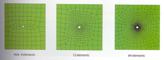
Hey Guys, We are going to dive a little more into the meshing. Bcoz this is a very important topic that needs to discuss with. When we are doing mesh on geometry. There are various types of bodies on them we need to do the mesh. In which it is having some critical areas where there is more stress concentration occurs. So we need some dense type of mesh over there.  Firstly let's talk about what is mesh density? It is nothing but the number of elements per unit area. As we know, if the density of mesh increases the computation time will go high.  So, here as we have discussed the meshing elements we know that the quad element has better accuracy than tria so here I have found this image in which it has the increasing elements on the same geometry. So, here you can see that as the number of elements increases near the hole. So now what we are getting through this. The geometry has a dimension of 1000*1000mm and a thickness of 10mm. We are going to pull it from the right side wit...

HOW TO START MESHING ??? TECHNIQUES AND FEATURES

  Hello Guys, In the previous one we have discussed mainly, the types of meshing in today's blog we will understand how to mesh and what should be done while meshing to improve the quality of the mesh and have an accurate result... so let's go There are various points that should one remember while carrying meshing which we are going to discuss... 1. Spend sufficient time studying geometry:  For carrying out the meshing in a good way we have to study geometry properly. Most of the time it is observed that most of the CAE engineers directly do to meshing job. That's the biggest mistake I have done in the past when I directly go with the meshing. Here is an imp step to understand the curvatures and other things of the geometry by which we can apply the options like proximity and curvature and also we can decide the element types by which. 2. Time: Nowadays it is very important to look at the clock. because it is very important according to the boss's and client's poin...

TYPES OF MESHING

Image
 Hey guys, Today we are going to talk about meshing, I know another meshing one blog yes... I know we already discuss some meshing concept but today we are exploring it a bit more... so let's start  We know why we carry out meshing and what its advantages also we had discussed about the DOF and nodes, elements blah blah... if you don't read it I am providing the link here check it out https://understandingfea.blogspot.com/2020/10/meshing-fem-and-types-of-elements.html So the basic purpose to carry out is to make calculations at finite points. We know that we have to carry out meshing for the various geometries and geometry can be different and complex.                     Then what to do in such cases, Lets explore it we know that our FEA problem which we are solving is needed to be easy and not very much complex and, if you have a complex problem then we need to identify how can we simplify it... We can simplify the ...

What is Non-linearities in FEA? & What are different types?

Image
 Hey guys Today we are talking about the most important topic i.e. the nonlinearity of FEA.  What is non-lineaities? We have talked about linear and non-linear analysis. And how they differentiate from each other. Every problem that we encountered in real life is non-linear. But for the sake of simplifying the problem, we do it with the linear analysis.  What is the linear analysis means? In which for solving any type of problem we considered that the force and the displacement (As an output) are changing linearly. As in the linear analysis the stiffness of matrix doest change it remains constant.                As in the non-linear analysis, there are different types of non-linear analysis. The nonlinearities vary or it depends on various factors there are various types of non-linearites such as a 1) Material nonlinearity 2) Geometric nonlinearity 3) Contact nonlinearity   1) Material nonlinearity As in Material nonlinear...

MESHING, FEM AND TYPES OF ELEMENTS

Image
 Hey guys, Let's talk about the meshing of FEA, FEM, and its types. That is really an important concept of FEA that every FEA analyst needs to know.                 The basic theme for the generation of mesh is to make the calculation at the finite no of point and then interpolate the result at the entire surface and domain.  For example the above dig. shows that if we have a surface and want to calculate the result then we cant calculate it bcoz of where in the domain having an infinite no of points and each point having 6 dof so the total equation created is infinite. In another way in dig 2 we are dividing the domain in some finite no of points and the equation generated is 48.               The Finite Element Method reduces dof from an infinite no of points to a finite no of points with the help of discretization i.e. meshing (Nodes & Elements) All calculation made at nodes and th...

WHAT IS DEGREES OF FREEDOM...

 Hey guys, Today we are talking about the degrees of freedom which is dof''s. The dof is the freedom of any point that it wants to move in a particular direction. T he maximum number of logically independent values, which are values that have the  freedom  to vary. In the CAD or designing of any component, it is very important to understand about the dof. If we don't consider it may lead to failure. Also in FEA, the dof is very important in terms of calculating the result of getting the proper values from the mesh. The principle of meshing works on the dof. In which each node has its own dof. We will be going to talk about the mesh and why mesh is important and how it works later on in detail. But in short, the mesh is the important part in which it divides the modal into the element and nodes so that at each node we can extract the result from it. The nodes are points created by elements. Going back to the dof, each node has its own dof. We know that we have the 12 no of...